Brief explanation on experiment
Shaking table test
2 span(6m x 2)elevated girder bridge models with 1/6.7 scale(1/s=1/6.7) supported by 3 piers with the same cross-sectional shape via rubber bearings(Fig.1-1) were designed based on the current Japanese seismic design code for highway bridges where the performance of the bridges is checked for the unidirectional design seismic accelerations applied in the longitudinal direction and that in the transverse direction, independently. According to the current seismic design code, limited plastification are permitted in the columns of the piers in the performance check under the Level 2 design earthquake waves that have the magnitude equivalent to those observed in the 1995 Kobe earthquake.
In the shaking table test, the time axis of the input acceleration waves are shortened by multiplying that of the actual earthquake waves by √1/s such that the magnitude of the response acceleration spectrum of the scaled models corresponding to that of actual bridges. This is to make the response stresses of the scaled models correspond with those of actual bridges.
As the piers in the models, 4 types of columns are used. That is, circular or stiffened square steel piers with or without in-filled concrete. The respective piers are referred to as hollow square pier, hollow circular pier, square CFT pier and circular CFT pier. In addition to these test piers, high strength piers are used to adjust input accelerations and a measuring system as well as to examine the behavior of rubber bearings installed in the elevated girder bridge model. The types of the columns together with the input acclerations are summarized in Table 1-1. The superstructure of the model is supported by 3 piers via rubber bearings. The superstructure is composed of 2 longitudinal main girders and 3 main cross girders. Each main cross girder of the superstructure is supported by two rubber bearings installed on the cross beam of each pier. To measure the reaction force and moment components of the rubber bearings, multi-axis load cells are inserted between the rubber bearings and the pier cross beams. The top of the column in a pier is rigidly bolted to the pier cross beam, while the column base is rigidly anchored to the shaking table. The weights installed on the superstructure are adjusted such that the axial force of the center column becomes larger than those of the end columns. This is to observe how the damages of the columns propagate from the center pier to the end piers. In the test, accelerations, displacements, forces, strains, respectively, of the bridge models are measured by accelerometers, reel-type transducers or laser transducers, and strain gages, respectively. As the bi-directional horizontal input acceleration waves, the magnified LG (longitudinal) and TR (transeverse) components of the Tsugaru wave observed at the Tsugaru Bridge during the 1983 Nihonkai-chubu Earthquake are used. The observed LG and TR components of the Tsugaru wave are magnified such that they correspond with the Level 2 earthquake wave. The first reason why the Tsugaru wave is selected is that its shaking duration is long and many repetitions of alternate seismic horizontal force components act on the bridge models. The second reason is that the Tsugaru wave has often been used for the shaking table tests and there exist a lot of test data under this wave.
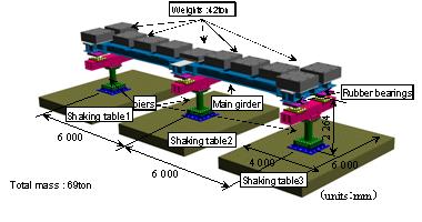
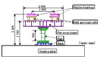
Fig. 1-1 2 span elevated girder bridge model used for shaking table test
Table 1-1 Column types and input acceleration waves used for shaking table test
| Columns used for bridge piers | Input acceleration waves |
|---|---|
| With hollow circular piers | Bidirectional horizontal components of the Level 2 earthquake |
| With hollow square piers | Bidirectional horizontal components of the Level 2 earthquake |
| With circular CFT piers | Bidirectional horizontal components of the Level 2 earthquake |
| With square CFT piers | Bidirectional horizontal components of the Level 2 earthquake |
Bi-directional cyclic loading test on rubber bearings
In view of the failure of rubber bearings observed during the 2011 Tohoku earthquake(Photo 1-2), a new tri-directional cyclic loading system primarily intended for bearings was developed at Nagoya Institute of Technology (Fig.1-2, Photo1-3). This loading system can apply arbitrary bi-directional horizontal displacement components and vertical load to a rubber bearing with keeping parallel the upper and lower steel plates of the rubber bearing. The system was newly made by attaching to the existing 3D loading system (Obata & Goto 2007) a new device that always keeps parallel the upper and lower steel plates of the rubber bearing under any bi-directional displacement components. Bi-directional behavior of the rubber bearings installed in the elevated girder bridge models was investigate in advance to the shaking table test and is reflected in the modeling of the bearings in the advanced numerical analysis.
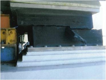 Photo 1-2 Failure of rubber bearings |
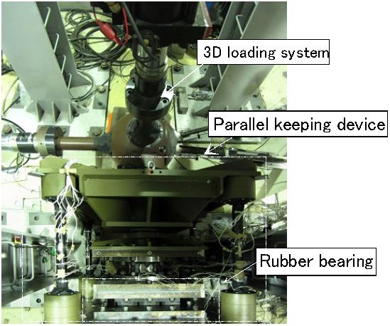 Photo 1-3 Bi-directional cyclic loading system) |
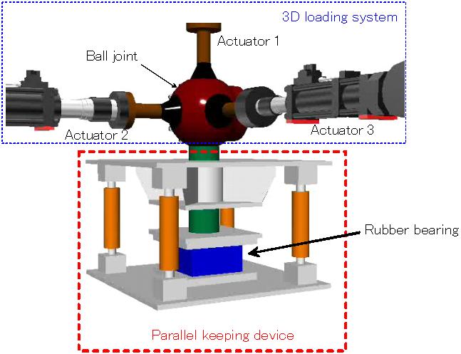 Fig.1-2 Bi-directional cyclic loading system) |
Copyright (C) N.I.T.Structural&Earthquake Engineering Lab. All Rights Reserved.